Eric Packman,
August 10, 2013
#hwdesigncontest #buildsomething
Project Li-Fi
My project was an attempt to replace my old nemesis, wifi, with an alternative that's safe, secure, fast and not prohibited by the CRTC. It occurred to me that if, for example, an LED driving multimode fiber optics can attain multi-gigabit speeds, why can't LED lighting in the house also communicate information, at least fast enough for home tasks? Turns out, it can. Once I install this in my house, I won't have to worry about who else is listening in on my network, I can just close the curtains. I won't have to compete for bandwidth with the neighbors or the microwave oven anymore.
This kind of technology can also be used to finally alleviate high-population density WiFi failures, like the failure we experienced at the hacking event itself – too many people were on the WiFi network, and it became quite challenging to gain Internet access. Every conference I've ever been to has serious rate shaping software, and has wifi issues regardless. Technology like this that can transmit with high throughput using LED-powered spot beams as indoor lightning AND as data sources can alleviate this simply by having as many LED sources as required per region.
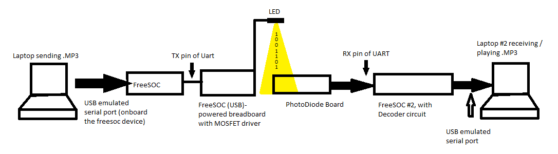
Project Overview
During the event, I used a Cypress 5lp based board, which is simply fantastic for rapid prototyping.
At the end of the hackathon, I was successfully able to transmit an MP3 from one laptop, and play it in real-time on a receiver laptop.
The project is actually quite light in hardware requirements, but as it's mostly analog-range electronics, it suffers greatly on the receiving side, mostly from capacitance and RF interference due to a suboptimal breadboard implementation. I'd love to try making some circuit boards with a proper ground plane, and very short traces in order to attempt to really crank up the bitrate.
A similar schematic to what I used can be viewed on upverter.com.
The Information-sender Circuit
The schematic for the transmitter was a simple n channel enhancement mode mosfet driving a CREE xlamp LED “warm white” element.
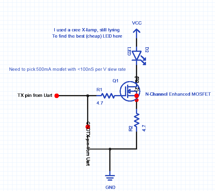
Vcc was 4.7V from my laptop's USB, and the entire circuit including the LED at 100% duty cycle used 110 mA. IE: The lamp was not very bright. I plan to upgrade to a higher current (but as low-as-possible voltage) LED for brighter PWM, thus higher gain at high switching speeds. Additionally, my search continues for the ideal (but inexpensive) switching mosfet.
I was originally going to build a verilog Manchester Encoding OOK system, but that proved unrealistic with the time constraints, and I quickly abandoned that idea, and went for a simple light-encoded UART instead. Essentially, data was transmitted via TTL RS-232, at 8 data bits, no parity, and 1 stop bit, from a vanilla freesoc UART module. The “TX” pin of this UART is hooked up to the gate of the mosfet, as shown in the schematic.
The information Receiver Circuit
The schematic for the receiver I made on the freesoc looked like this:
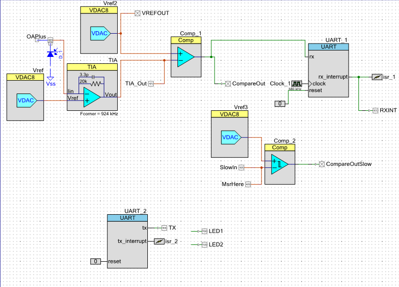
For the “real” board, I plan to use discrete components on a proper circuit board that I plan to make through upverter. Details are shown in the upverter schematic linked above, on the right-hand side of the drawing.
The Demo
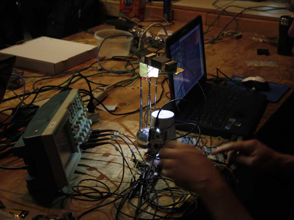
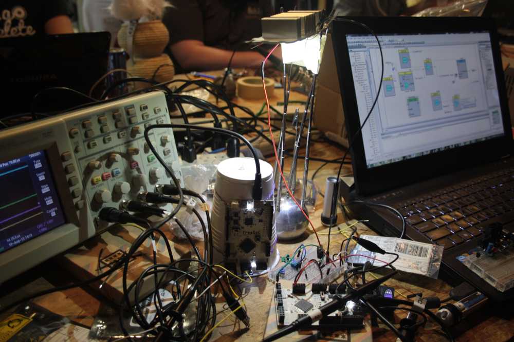 When the demo began, I started transmitting the MP3 on the transmitter Laptop. The LED light, which is normally on at 100% duty cycle, suddenly dimmed somewhat, as the LED was turning on-and-off (OOK / PWM) while transmitting the data. The receiver, a fraction of a second later, began playing the music (Pink Floyd, comfortably numb – videos of this seem to be popping up on twitter & elsewhere lately). The crowd “ooh”ed and “aah”ed as I passed my hand between the LED and the photodiode and the music stopped immediately. I demonstrated how other light sources did not interfere with the data transmittion unless they were intense. I showed a flashlight 4 inches away from the detector, lit at the same time as the LED-encoded information streamed in, without any interruption. A friendly volunteer showed how an ultra violet laser pointer aimed at the photodiode could finally saturate the detector, and introduce errors in the data stream as it caused audible pops in the music.
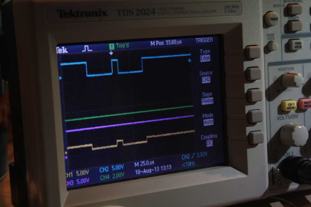
The picture below shows the oscilloscope inputs. The yellow line was taken from the TTL “TX” pin on the transmitter, and the blue line shows the input to the “RX” pin on the receiver, just before the UART. The two signals match, showing a successfully transmitted byte. Yes, the photo is boring, but people who were there and saw the live action version all loved it :)